ISO 8256 | ASTM D1822 Tensile Impact Test
The ISO 8256 and ASTM D1822 standards describe the procedure for determining the tensile impact strength of plastics and the performance of tensile impact tests.
Tensile impact tests provide a material property based on the impact energy, which is determined under tensile stress on standardized test specimens with a relatively high deformation rate. When using the same pairings of pendulum and yoke sizes, the result is a good level of reproducibility of the test results. For various combinations, the standards specify correction methods that enable approximate comparability.
Tensile impact tests according to ISO 8256 and ASTM D1822 can be used for rigid plastics (according to the definition in ISO 472), but are particularly useful for flexible specimens made of films or sheets, as well as soft or semi-rigid plastics that are too flexible or too thin for the Charpy method according to ISO 179 or ASTM D6110 or the Izod method ISO 180 or ASTM D256 and do not result in a specimen break and therefore no result even with notched specimens.
Test methods Test equipment and test requirements Video Specimens and dimensions Downloads Customer projectsRequest a consultation
Test method to ISO 8256 and ASTM D1822
The ISO 8256 standard specifies two different test methods:
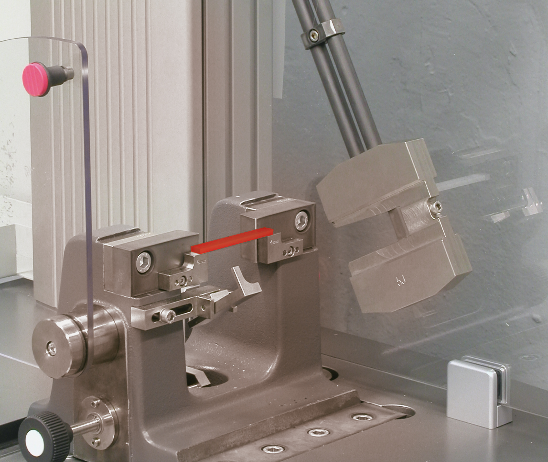
- Method A works with a test arrangement in which the specimen is fastened on one side in a defined position in a standing clamping fixture. A rigid yoke with a fixed mass is attached to the other side of the specimen. During the test, the pendulum hammer strikes the yoke, which causes it to strongly accelerate. This stretches the specimen in tensile direction until it fails.
- Method B is borrowed from the ASTM D1822 standard and works with the so-called specimen-in-head method. The specimen is fastened in the pendulum hammer and also provided with a defined yoke on its opposite side. Together, the specimen, yoke and pendulum form a drop weight. The yoke is stopped abruptly at the impact position, while movement of the specimen and the pendulum hammer continues and the specimen is stretched in tensile direction to the point of failure.
Normally, method A is used in connection with the ISO 8256 standard, while tests to ASTM D1822 are always performed with the specimen-in-head method.
Tensile impact tests are also offered in the form of instrumented tests, that is, with fast force measurement. However, there is no standard for this yet.
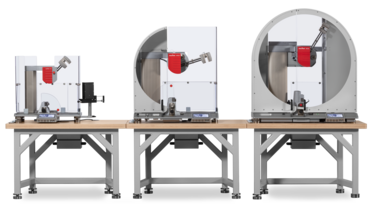
ISO 8256 and ASTM D1822: test equipment and test requirements
Pendulum impact testers, which are defined in detail in the ISO 13802 standard, are used for conventional tensile impact tests in accordance with ISO 8256 and ASTM D1822. This supports a strong level of reproducibility of tests performed using different types of test equipment and different laboratories, operators and locations.
As is the case with the Charpy impact test ISO 179 ASTM D6110, the measurement principle is based on a pendulum hammer with specified energy capacity and drop height, which releases part of its kinetic energy when it penetrates the specimen. As a result, the pendulum hammer does not return to the original drop height after the impact. The measured height difference between drop height and height of rise therefore becomes a measure of the energy absorbed. By determining the drop height, the impact velocity is also defined so that the tests are performed with reproducible strain rates.
A special feature of the tensile impact test is correction of the centrifugal work absorbed by the yoke. This correction is based on the assumption of an elastic impact. In practice, however, there is an impact that has a plastic component in addition to the elastic component, so this correction remains an approximation. A direct comparison of characteristic values should therefore be carried out on an identical pairing of pendulum hammer and yoke size.
Each pendulum hammer may be used in a range of 10% to 80% of its initial potential energy. If several pendulum hammers meet this condition for testing a material, which is usually the case from the overlapping working ranges of the various pendulum hammers, the pendulum hammer with the greatest initial potential energy is used. This ensures that the reduction in speed during the impact process is minimized.
The type of measurement implies that all energy losses are attributable to the specimen and the yoke. It is therefore important to minimize, correct, or completely eliminate all external sources for error. There are strict specifications in ISO 13802, as well as checks that are part of regular calibrations, regarding friction losses that inevitably occur due to air friction and friction at the bearing points of the pendulum hammer. The correction values are measured and assigned to the respective pendulum hammer. Sufficient mass and a vibration-free installation of the pendulum impact tester on a very stable laboratory table, on a worktop bolted into a solid wall, or a masonry platform are essential for the quality of the measurement. Internal vibrations in the instrument are minimized by design. ZwickRoell uses pendulum hammers with double rods made of unidirectional carbon materials, which are very low in mass and at the same time offer optimum stiffness of the pendulum rods.
Video: Pendulum Impact Testers for Plastics Testing
ZwickRoell’s HIT series pendulum impact testers for the plastics industry offer a high-precision, cost effective solution. The pendulum impact testers are available from 5 to 50 joules and enable not only the standard-compliant performance of tensile impact tests according to ISO 8256 and ASTM D1822, but also Charpy, Izod and Dynstat tests according to ASTM, ISO and DIN.
Specimens according to ISO 8256 and ASTM D1822
ISO 8256 defines a total of five different specimens.
- Type 1 and 4 are the preferred options for method A
- Type 2 and 4 are the preferred options for method B
- Type 3 has a parallel middle section, which is square with an edge length of 10 mm and is well suited for strain measurements with DIC systems.
- Specimen type 5 includes additional stop surfaces on the shoulder, which facilitate precise alignment and allow for form-fit force transmission with rigid materials and sufficient specimen height.
ASTM D1822, which is carried out in method B, describes 2 specimens type S and type L for tensile impact tests.
| Standard | Type | Note | l3 mm | L/L2 mm | b2 mm | b1 mm | l0 mm | Shape |
|---|---|---|---|---|---|---|---|---|
| ISO 8256 | 1 | Preferred method A, notched | 80±2 | 30±2 | 10±0.5 | 6±0.2 | - | |
| ISO 8256 | 2 | Preferred method B | 60±1 | 25±2 | 10±0.2 | 3±0.05 | 10±0.2 | |
| ISO 8256 | 3 | Square middle parallel part 10 mm edge length; for strain measurement with DIC systems | 80±2 | 30±2 | 15±0.5 | 10±0.5 | 10±0.2 | |
| ISO 8256 | 4 | Preferred methods A and B | 60±1 | 25±2 | 10±0.2 | 3±0.1 | - | |
| ISO 8256 | 5 | Rigid materials with sufficient specimen height | 80±2 | 50±0.5 | 15±0.5 | 5±0.5 | 10±0.2 | |
| ASTM D1822 | S | Method B | 63.5 (2.5”) | L= 25.4 (1") | 9.53 or 12.7 (0.375 or 0.5”) | 3.18±0.03 | - | |
| ASTM D1822 | L | Method B | 63.5 (2.5”) | L=L2=25.4 (1") | 9.53 or 12.7 (0.375 or 0.5”) | 3.18±0.03 (0.125± 0.01") | 9.53±0.05 |
FAQs about impact tests on plastics
| Dynstat | Tensile impact - Tensile-in-head method | Tensile impact | Izod and Unnotched canilever beam impact | Charpy |
|---|---|---|---|---|
| DIN 53435 | ASTM D1822 / ISO 8256 - method B | ISO 8256 - method A | ASTM D256 / ASTM D4812 ISO 180 | ASTM D6110 / ISO 179 |
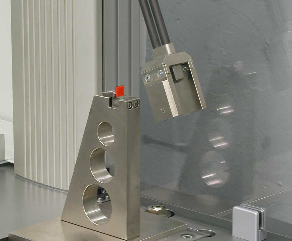 | 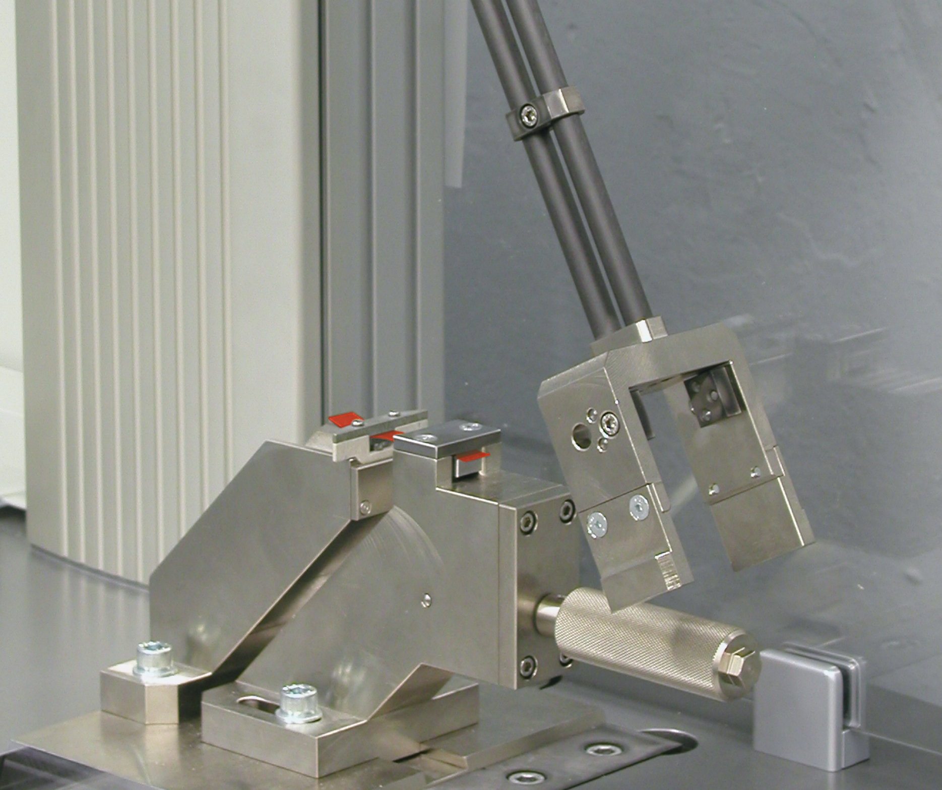 | 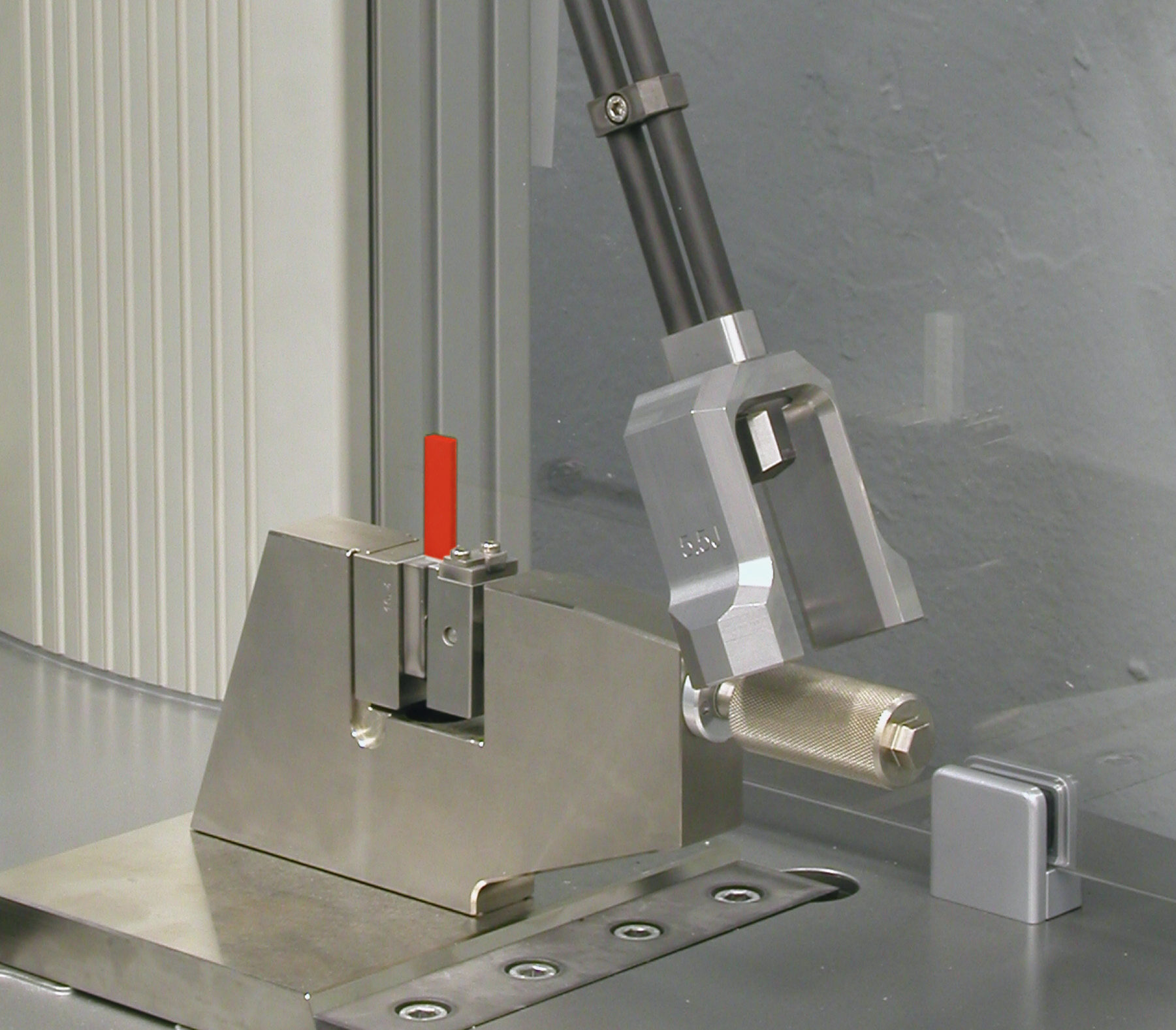 |  | |
| For small specimens machined from components | Specially suited for flexible specimens, which according to Izod and Charpy, do not produce a specimen fracture, and therefore no results. | |||
