Testing of Solar Cells
Tremendously high quantities, long life expectancy, and very few to no testing guidelines— this is the current situation in the photovoltaics industry. Testing is essential for companies who want to remain players in this fiercely competitive market and achieve the promised performance data and life expectancy while offering the lowest prices. Solar cells can survive the tremendous drop in prices in recent years only by improved quality, cost-effective production and better safety.
Challenge
Solar cells are exposed to environmental extremes on a daily basis. Rain, hail, storms, and large fluctuations in temperature should not impair the functionality of the product. They must be able to withstand the weight of snow, ice, and installation to achieve a desired life expectancy of 40 years without damage. These expectations are high for both electrical and mechanical characteristics. However, test standards for mechanical requirements for components do not exist. Apart from internal individual contract provisions between suppliers and manufacturers, standardized quality assurance guidelines for solar cells do not exist. The lack of standards and individual customer needs means customized test equipment and test are needed. This is where materials testing experts come into play.
Examples of Testing Solutions
To understand how destructive material testing is used in solar cell and module manufacturing, examples of production control for the individual stages of production of thick-film cells testing applications are introduced.
Solar cells or photovoltaic cells are electrical components that convert the radiant energy contained in light directly into electrical energy.
Principal Types:
- Thick-film solar cells are made from monocrystalline or polycrystalline silicon. They are widely used in Central Europe because of their high efficiency (over 20%). Additionally, they are characterized by a high degree of efficiency per surface area unit. For example, approximately 8 sq. m. of roof area is needed to produce an output of 1 Kwp. The amount of material and energy required to manufacture these modules is relatively high, therefore quality assurance is essential.
- Thin solar cells exist in a number of variations regarding substrate and vapor-deposited materials: amorphous or micro-crystalline silicon (a-Si, μ-Si), gallium arsenide (GaAs), cadmium tellluride (CdTe), or copper-indium-(callium)-sulfur-selenium compounds (CIGS). Thin-film cells differ from solar cells based on crystalline silicon wafers primarily in their production process and in the film thickness of the materials used.
- Organic solar cells (made of plastics with semiconductor properties)
Testing requirements may vary considerably according to the type of solar cell, as the various technologies in use can in some instances lead to fundamentally different designs.
Peel test on Tedlar film
Plastic EVA (ethylene vinyl acetate) or cast resin films are laminated on both sides to form waterproof corrosion protection, while a Tedlar® film or a glass sheet on the rear provides additional protection for the module. The strength of the bonds is tested by means of a 90° peel test, in which the Tedlar® film is clamped into a screw grip and pulled off the glass plate. A single-column testing machine is suitable for this test as it allows glass sheets of various sizes to be tested without difficulty. This test is carried out during production to check that machine parameters are set correctly. It is also used in goods inwards checks and during requalifying tests after expiry of the use-by date. To meet the standards, the Tedlar® film must withstand peel forces up to 250 N.
Pull-out test between junction box and connecting cable
Various safety tests are recommended for the completed module, including strength testing the frame structure, determining the press-in and extraction forces of the corner brackets, pull-out tests on electrical connections and tensile, compression and flexure tests on the mounting system for attaching the module. Cable pull-out tests on the junction box can be performed using a 2-column testing machine from Zwick’s Allround series. The junction box is retained in special specimen holders, while the connecting cable is held in screw grips and pulled out of the box using forces up to 5 kN.
Punch test on toughened safety glass to ISO 614 Form A and B
In the puncture test a 25x25 mm glass sheet is positioned in a double ring flexure test kit (consisting of support and load ring and stop pins for fixing the specimen). A die is then used to load the specimen up to break. The metal container prevents glass splinters from entering the machine drive. This test is carried out as per standard using a 2-column testing machine with a maximum force of 50 kN.
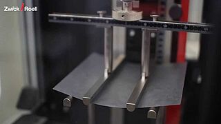
ProLine with 4-point flexure test on structural glass to EN 1288-3
- Either a static puncture test to EN 1288-5 or a 4-point flexure test to EN 1288-3 can be used to test the safety of the glass sheet employed.
- A ZwickRoell AllroundLine testing machine is used for both tests, which requires the incorporation of safety devices to prevent damage or injury due to flying glass splinters.
- This testing system has been specially assembled for use in determining the flexural strength of flat glass according to EN 1288-3 and meets all requirements of the standard. All anvils and bending rollers can be rotated freely and are to the required dimensions and separations.


