- 1 kN - 250 kN
- 10 - 2,500 Nm
- Torsional vibration
- ASTM F1717
- ASTM F2706
- ISO 12189
- ISO 7206-6
What is torsional vibration?
Torsional vibrations are vibrations that can occur in a component or a system when it is subjected to torsion. They occur when part of a system is twisted to create a torsional load that causes the system to spring back or the torsional load to be reapplied.
In many cases, the torsional load is also superimposed with an axial load (static or dynamic). This superimposed dynamic loading is often used in the simulation of real-life conditions that affect components, for example when testing spinal implants.
Axial torsion testing machines from ZwickRoell
Our axial torsion testing machines cover a wide range of torsion tests and can be adapted to your specific applications.
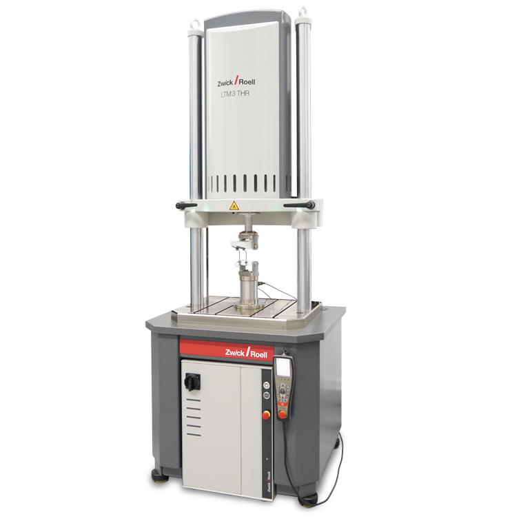
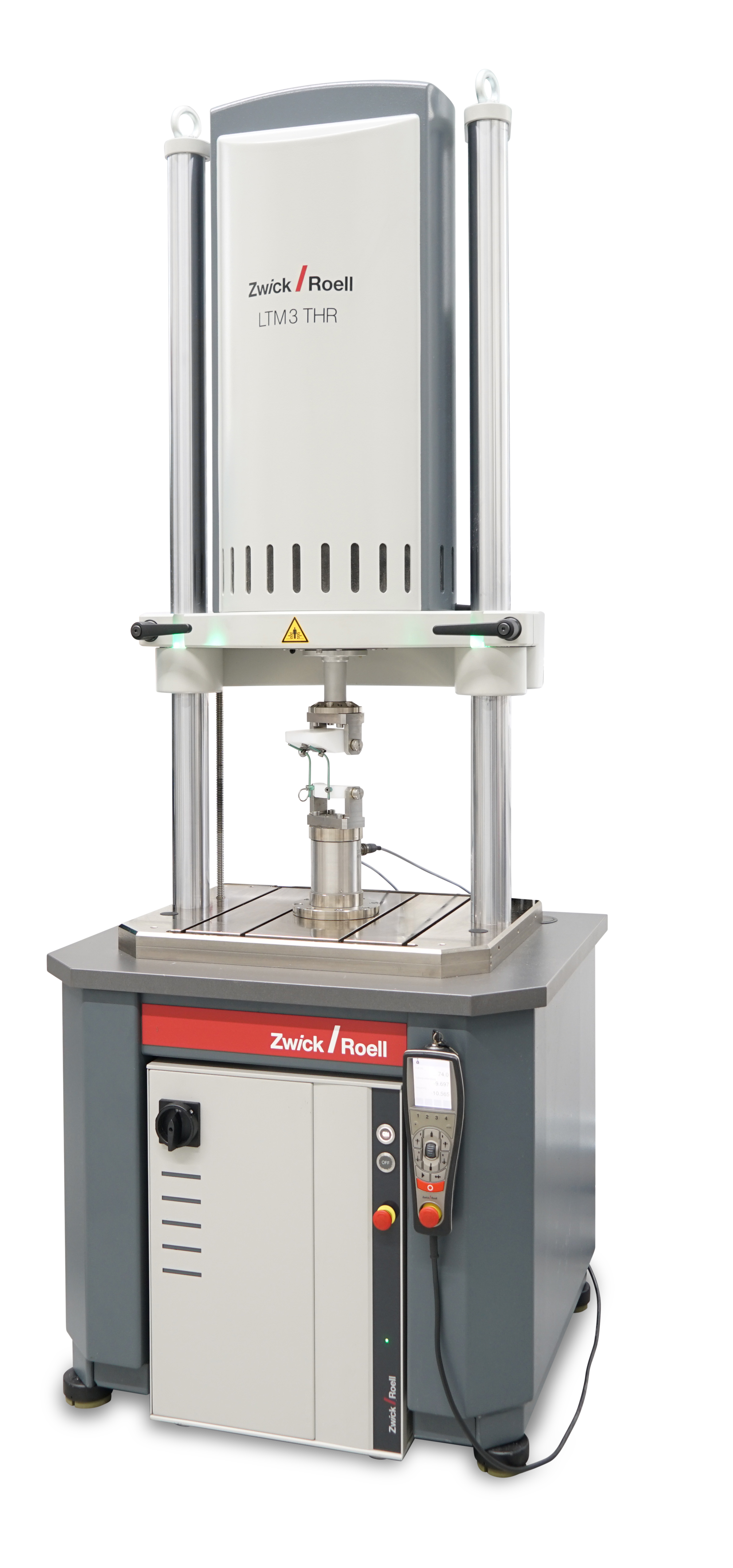
- Electrodynamic torsion testing machine LTM Torsion
Electrodynamic torsion testing machine with a drive based on linear-motor-technology. It is equipped with a 10 Nm, 20 Nm, 30 Nm, 50 Nm or 100 Nm torsion drive for test loads from 1 kN to 10 kN. - Servohydraulic torsion testing machine HCT
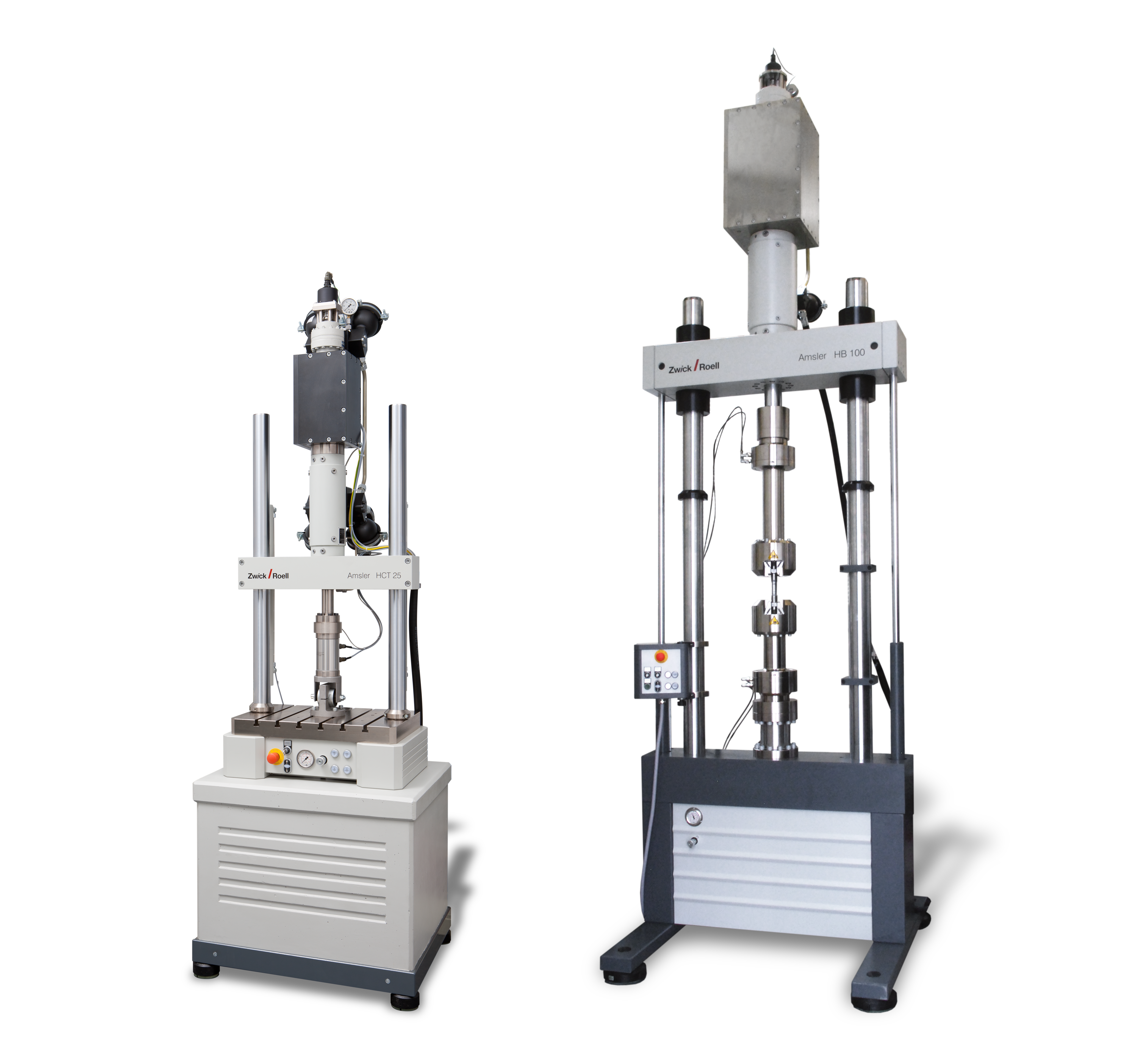
The servohydraulic torsion testing machine (table-top model) is equipped with a 250 Nm torsion drive. It can be used for the determination of the torsional vibration for test loads up to 25 kN. - Servohydraulic torsion testing machine HBT
The servohydraulic torsion testing machine (floor-standing model) is equipped with a 2,500 Nm torsion drive. It can be used for the determination of the torsional vibration for test loads up to 250 kN.

testXpert R – our software for dynamic testing
In the testXpert R software, all test programs have a workflow-based structure and are aligned with real workflow processes in the lab. This setup guides the user through the test with logical and traceable steps. In addition, both simple and complex test sequences can be intuitively created and executed using the graphical block editor of the dual-axis sequencer testing software.
Common standards for tests with torsional vibrations
- ASTM F1717 - Standard Test Methods for Spinal Implant Constructs in a Vertebrectomy Model
When tested according to the ASTM F1717 standard, spinal implants are subjected to a multiaxial fatigue test in addition to static tests. - ASTM F2706 - Standard Test Methods for Occipital-Cervical and Occipital-Cervical-Thoracic Spinal Implant Constructs in a Vertebrectomy Model
The ASTM F2706 standard describes static test methods as well as fatigue tests and the superimposed torsion test on occipital-cervical and occipital-cervical-thoracic spinal implants. - ISO 12189 - Mechanical testing of implantable spinal devices—Fatigue test method for spinal implant assemblies using an anterior support
The ISO 12189 standard describes fatigue testing of flexible spinal implant assemblies and biomechanical fatigue testing of all types of spinal implant assemblies. - ISO 7206-6 - Implants for surgery—Partial and total hip joint prostheses—Part 6: Endurance properties testing and performance requirements of neck region of stemmed femoral components
The ISO 7206-6 standard is used for multiaxial fatigue tests on the neck region of hip joint prostheses. This test simulates a well ingrown femoral stem.
Technical overview
| LTM Torsion | HCT | HBT | |
|---|---|---|---|
 |  |  | |
| Drive | Electrodynamic | Servohydraulic | Servohydraulic |
| Model | Floor-standing testing machine | Table-top testing machine | Floor-standing testing machine |
| Max. axial force | 1 kN 2 kN 3 kN 5 kN 10 kN | 10 kN 25 kN | 50 kN 100 kN 250 kN |
| Torsion drive, dynamic | 10 Nm 20 Nm 30 Nm 50 Nm 100 Nm | 100 Nm 250 Nm | 500 Nm 1,000 Nm 2,500 Nm |
| Angle of rotation | Continuous rotation | ±50° | ±50° |
| Torsion drive can be retrofitted | ✓ | - | - |
| Typical applications |
|
|
|
| Type | LTM 1 T + 400 mm1 | LTM 2 T + 400 mm1 | LTM 3 T + 400 mm1 | |
| Item No. | 3014181 | 3014182 | 3014183 | |
| Test load Fmax dynamic | ± 1000 | ± 2000 | ± 3000 | N |
| Test load Fmax static, continuous | ± 700 | ± 1400 | ± 2100 | N |
| Maximum frequency2 | 100 | 100 | 100 | Hz |
| Piston stroke | 60 | 60 | 60 | mm |
| Speed range | 2 | 2 | 1.5 | m/s |
| Positioning accuracy and repeatability | ± 2 | ± 2 | ± 2 | μm |
| Torsion drive | ||||
| Moment, dynamic | ± 10 | Nm | ||
| Moment, static continuous | ± 7 | Nm | ||
| Rotations | ± 500 | |||
| RPM, max. | 100 | 1/min | ||
| Moment, dynamic | ± 20 | ± 30 | ||
| Moment, static continuous | ± 14 | ± 21 | ||
| Rotations | ± 500 | ± 500 | ||
| RPM, max. | 100 | 100 | ||
| Test frame | ||||
| Test area | ||||
| Test area width | 460 | |||
| Test area width | 460 | mm | ||
| Test area | ||||
| Test area width | 460 | |||
| Overall height of testing machine, max. (A) | 2775 | 2775 | 2775 | mm |
| Overall height of the test frame, max. (B) | 1988 | 1988 | 1988 | mm |
| Overall width | 800 | 800 | 800 | mm |
| Overall depth | 700 | 700 | 700 | mm |
| Height of mounting table (C) | 692 | 692 | 692 | mm |
| Column diameter | 65 | 65 | 65 | mm |
| Frame stiffness at 1000mm crosshead separation | 24 | 24 | 24 | kN/mm |
| Overall weight3 | 510 | 510 | 550 | kg |
| Test area height, max. (D) | 1125 | 1125 | 1125 | mm |
| Test area height without load cell, max. (E)4 | 1065 | 1065 | 1065 | mm |
| Test area height with load cell, max. (F)4 | 905 | 905 | 905 | mm |
| Top crosshead adjustment | Motorized | |||
| Top crosshead clamping | Manual | |||
| Crosshead clamping electrically monitored | Yes, with signal indicator | |||
| General information | ||||
| Max. noise level at 1 m distance5 | < 63 | < 63 | dB(A) | |
| Typical noise level at 1 m distance5 | < 46 | < 46 | dB(A) | |
| Max. noise level at 1 m distance5 | < 63 | |||
| Typical noise level at 1 m distance5 | < 46 | |||
- Extended load frame - base frame (1055466) and supplementary mass (1055467) are absolutely necessary
- Depending on load ratio (r-ratio) and test amplitude
- Testing machine with base only, without electrical cabinet, tools, and options
- Middle piston position
- Depending on the required output, the environment, test arrangement, type of test, frequency of the specimen, determined in a free field in accordance with DIN EN ISO 11205
| Type | LTM 10 T Standard | LTM 10 T + 250 mm | |
| Item No. | 3011465 | 3011466 | |
| Test load FmaxDynamic | ± 10000 | ± 10000 | N |
| Test load Fmaxstatic, permanent | ± 7000 | ± 7000 | N |
| Maximum frequency1 | 100 | 100 | Hz |
| Piston stroke | 60 | 60 | mm |
| Speed range | 1 | 1.5 | mm/min |
| 1.0 | m/s | ||
| Positioning accuracy and repeatability | ± 2 | ± 2 | μm |
| Torsion drive | |||
| Moment, dynamic | ± 100 | ± 100 | Nm |
| Moment, static continuous | ± 70 | ± 70 | Nm |
| Rotations | ± 500 | ± 500 | |
| RPM, max. | 100 | 100 | 1/min |
| General information | |||
| Max. noise level at 1 m distance2 | < 68 | < 68 | dB(A) |
| Test frame | |||
| Overall height of testing machine, max. (A) | 2919 | 3169 | mm |
| Overall height of the test frame, max. (B) | 1980 | 2230 | mm |
| Overall width | 860 | 860 | mm |
| Overall depth | 850 | 850 | mm |
| Height of mounting table (C) | 720 | 720 | mm |
| Column diameter | 65 | 65 | mm |
| Frame stiffness at 1000mm crosshead separation | 300 | 300 | kN/mm |
| Overall weight3 | 1100 | 1125 | kg |
| Test area | |||
| Test area width | 460 | 460 | mm |
| Test area height without load cell, max. (E)4 | 983 | 1233 | mm |
| Test area height with load cell, max. (F)4 | 830 | 1080 | mm |
| Top crosshead adjustment | Motorized | ||
| Top crosshead clamping | Manual | ||
| Crosshead clamping electrically monitored | Yes, with signal indicator | ||
- Depending on load ratio (r-ratio) and test amplitude
- Depending on the output required, environment, test arrangement, type of test, frequency of the specimen, determined in free field according to DIN EN ISO 11205
- Testing machine with base only, without electrical cabinet, tools, and options
- Middle piston position
| Test area height | Standard | Extended by 250 mm | Extended by 500 mm | |
| Dynamic nominal force | 25 | 25 | 25 | kN |
| AG100 – max. height of the test frame | 2310 | 2560 | 2810 | mm |
| AK – tilted dimension for erecting | 1750 | 1995 | 2240 | mm |
| B – max. width of test frame | 660 | 660 | 660 | mm |
| C – max. depth of test frame | 500 | 500 | 500 | mm |
| D1 – distance between columns | 460 | 460 | 460 | mm |
| E – column diameter | 65 | 65 | 65 | mm |
| F – height of top edge of lower crosshead | 215 | 215 | 215 | mm |
| G – max. height of test area1 | 1000 | 1250 | 1500 | mm |
| H – max. height of work test area2 | 910 | 1160 | 1410 | mm |
| J – crosshead adjustment path | 600 | 600 | 600 | mm |
| K – weight3 | 435 | 450 | 465 | kg |
| Frame stiffness at 1000mm crosshead separation | 300 | 300 | 300 | kN/mm |
| T-slot connection dimension | To DIN 508 M10 x 12, distance 80 mm Ø 70 mm, 6 x M8 (only 6 screws) and Ø 115 mm, 4 x M8 | |||
| Clamping/ adjustment: manual/hydraulic | 9352754 | 9361104 | 9362594 | |
- Distance between upper and lower crossheads
- Distance between piston flange and lower crosshead with piston retracted
- Weight with actuator
- Fixed mounting onto base required, recommended base 935284

